Low Pressure Fuel System Problems on Second Generation Cummins Diesel Rams
We all see much discussion on the TDR web forums and in the TDR publications regarding performance/drivability issues, which are often traced to a low pressure fuel delivery problem. Although the narrative that follows is specific to the 12-valve Turbo Diesel trucks, model year ’94 to early ‘98 (pre 24-valve engine), the discussion on the components from the fuel tank (float and sending unit) to the fuel transfer pump apply to all Second Generation trucks.
The term low pressure fuel delivery system covers the components from the fuel tank up to the truck’s fuel injection pump and from the injection pump back to the fuel tank. Common problems that will be discussed:
- Fuel level sending unit
- Fuel heating element
- Fuel transfer pump
- Overflow valve
- Fuel return line
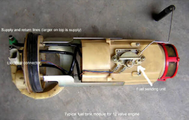
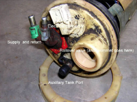
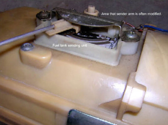
Let’s start at the beginning, the fuel tank. The fuel tank is approximately 34 gallons and made of an injection molded-type plastic material. The tank utilizes a fuel tank module with an integral fuel level sending unit. Carter (Federal-Mogul company) is typically the fuel tank module manufacturer; Walbro manufactures the sender. The module is installed vertically in the fuel tank and is retained by a large plastic nut and o-ring gasket to the threaded top of the fuel tank. The module has a lower half that can float up and down somewhat on a slide system. The purpose of the float is to prevent erratic fuel gauge readings due to fuel slosh when driving off-road. It also serves as a small basket, which will hold approximately one quart of fuel. This prevents air entrainment in the fuel system when the tank level is low and steep approach angles are tackled. The top of the module has ports for fuel supply (3/8”) and fuel return (5/16”), a rollover valve/tank vent, an auxiliary fuel port and an electrical connector. The only serviceable parts on the module are the sending unit and the rollover valve and its grommet. The sending unit is notorious for the wiper contact area to wear out, which results in erratic fuel readings or fuel gauge malfunction. A sender-testing chart is shown should you desire to test your sender while the truck module is removed from the fuel tank.
| Model Year of Truck | Sender Ohms at Full | Sender Ohms at Empty | Low Fuel Indicator Lamp Ohms |
| ‘94-‘97 | 0 +/- | 100 +/- | 65 +/- |
| ‘98-‘02 | 20 +/- | 220 +/- |
Sometimes the use of an old-school analog multimeter will catch a dead or bad spot as the sender is moved up and down. The needle will falter or jump at the contact failure. Digital multimeters (DMM) are great tools, but my old analog meter still gets plenty of use for tasks like this. The DMM is constantly auto-ranging for accuracy in a specific reading versus the analog meter holding a steady reading. Now you have an excuse to purchase both types of multimeters!
Looking back in my TDR index, I see that members have been bothered by this problem since Issue 16 in the Spring of ’97 when member Russell Caya did a how-to on fuel tank removal. Other memorable articles: Issue 26 where Mel Lang took the sending unit apart in an attempt to understand why it was/is problematic.
My look back at these old sources of information did not reveal a shadetree repair procedure. Perhaps the labor and time involved to remove the unit dictates that one should install a new sending unit rather than hope a repair would work.
Perhaps the labor and time involved to remove the unit dictates that one should install
a new sending unit rather than hope a repair would work.
Oops . . . I’ve gotten a bit ahead of myself. I’ve got you diagnosing the fuel tank sending unit, but I haven’t given you some tips on removing the fuel tank, much less the fuel tank module which houses the sending unit. I prefer to drop the tank from the truck rather than lifting the truck bed. A tank with a couple of gallons can be a circus to balance, even with a large floor jack and a four-foot section of 2x12 or similar sized plywood, so it’s nice to drain the tank. My “Rube Goldberg tank drainer” idea was first presented by TDR writer Joe Donnelly in Issue 37, page 45. “Unfortunately many of us have bed-mounted fuel tanks, toolboxes, fifth-wheel hitches, etc., making the bed-lift method impractical. In that event, run the fuel low, and remove the filler neck (it has a check ball in it so the hose won’t snake down in to the tank). Put a piece of 3/8” hose into the tank, cut a whistle near the end, and blow air through the whistle with compressed air. This will start fuel flow and if your catch can is lower than the tank, it will flow until the tank is virtually empty.”
Hard plastic lines (supply and return) of a quick-connect variety connect to the module and run along the frame rail (this plastic line mates to a metal or braided line on some models). The lines then mount onto a bell-housing bracket. Then they bend around the bell housing where a short length of 3/8” rubber fuel line provides a fuel supply to the fuel heater line that extends behind the fuel filter. Due to the age of the 12-valve truck, careful inspection is necessary from the tank to the fuel heater/strainer, to ensure that there are no leaks in the fuel lines.
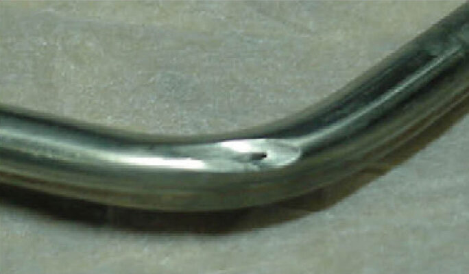
I recall a discussion (Issue 44, page 32) where Brandon Parks at Geno’s Garage had a lengthy battle with a hard-to-start ’97 12-valve truck. After weeks of troubleshooting he did a close inspection of the metal fuel supply line coming from the tank as it turned upward by the firewall. A pin hole caused by years of chafing was the problem.
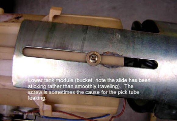
The module has metal pipes exiting the top of the module (supply and return) and has hard plastic tubing coils that extend to the bottom of the module where a removable screen covers the pickup and return. Most of them that I’ve dissected have a one-way check valve in the fuel pickup to assist in holding fuel prime. Many members have noted that these lines sometimes chafe and develop a pinhole, which allows for fuel aeration, not a good thing! The perforated tubing seems to have rubbed on a sharp edge, or on the mounting hardware for the lower float we previously discussed. The return also returns fuel to the bottom of the module (above tank bottom about ¼”). This is preferable, as it allows returned fuel to be released into the remaining fuel rather than spraying on the tank’s upper surface introducing foam and air.
Permit me to further digress: I recently made a road call to visit a sick ’95 model truck. The owner complained of a tapping noise and suspected connecting rod since the truck showed about 250,000 on the odometer. Over the phone when he held it near the source of the noise it sounded to me like a worn out lift pump tapping away on the cam lobe. The problem was missing fuel line routing brackets, which mount to the bell housing. It seems that the clutch had been recently changed and I assume the technician was speeding along attempting to “beat the book” (flat rate) and didn’t see the need to attach the awkward brackets. The supply and return were chattering away on the bell housing which was driving its owner to near insanity. Some zip ties and split pieces of fuel line temporarily solved the problem while the replacement brackets were ordered.
Again, due to age, the fuel heater/pre-filter is a common repair area on 12-valve Ram Turbo Diesels.
Again, due to age, the fuel heater/pre-filter is a common repair area on 12-valve Ram Turbo Diesels. TDR member Joe George showed us his method for finding a problematic air leaks at his fuel heater several issues ago (compressed air and a bucket of water). Joe’s dilemma was much like Brandon’s. Quoting from Issue 44, page 49, “I removed the fuel filter assembly (with the attached fuel heater and fuel pre-filter) from the truck. I applied 30psi of air to the assembly and lowered it into a bucket of water. Instantly, I observed a stream of bubbles rising from the fuel heater electrical connector. The connector had a crack in it, causing the lift pump to suck air into the fuel system. Without the removal of the assembly and the pressure test, I’m not sure I would have found this rare problem.”
The fuel heater warms the fuel if the fuel temperature is below 40° and shuts off when the fuel temperature reaches 80°. The heater draws about 300 watts at 0°. This should help to prevent fuel gel in sub-zero climates. Should your fuel heater fail, it can be removed or eliminated. The pre-filter bowl is removed (using a short 17mm box combination wrench), and then a 8mm hex wrench is used to remove the shoulder bolt that retains it to the fuel heater casting. Once the fuel heater is removed the pre-filter bowl should spin onto the pre-filter base, the heater can be unplugged and you should be on your way.
The pre-filter assembly is attached to the engine block with the transfer lift pump cap screws. Fuel comes into the top of the unit via a short metal supply line, which attaches to the short length of 3/8” fuel line. It then passes through the pre-filter screen, then the fuel heater then back out through a port and over to the transfer lift pump. This connection is made by a rubber supply line elbow that makes a sharp ninety-degree bend. I change this rubber elbow (item 11) when a transfer lift pump is serviced. Often this line is a major source of air leakage and subsequent fuel aeration.
As confirmation of my replace-the-elbow service technique, I had a discussion with a friend who is a competent technician. He had replaced a lift pump and now the truck would not restart. He stated that the lift pump would raise fuel up to the air bleed port on the fuel filter outlet, but with many bubbles rather than a clear stream of fuel. After we discussed probable causes, he called me back a short time later to report his findings. Sure enough, the rubber elbow was sucking air when the lift pump was manually primed. He also noted fuel weeping into the electrical connector on the fuel heater and a bad seal at the upper base and the upper heater “quad ring” (o-ring with square vs. round sides). Since he was short of parts, he removed the constant tension clamps and added gear-drive type clamps to the rubber line and removed the fuel heater and upper o-ring. After about twenty strokes on the primer and the truck started right up.
The next component, the heart of the low pressure fuel system for 12-valve owners, is the fuel transfer or lift pump. (Note to 24-valve owners: you can stop reading at this point. I don’t want to discuss your electronic fuel transfer pump.) The lift pump is a piston style pump typically manufactured by Carter. It is designed to provide about 25psi to the fuel filter. It contains a manual primer and integral check valves that prevent prime loss and pressure delivery as fuel exits the pump. The pump is actuated by a plunger tappet, which rides on an eccentric engine camshaft lobe. Often as the pump ages the check valves wear and the plunger springs weaken. This can cause internal as well as external air and fuel leaks and a loss of fuel prime. Additionally, the fuel volume and/or pressure can diminish to a level which will cause sub-par engine performance. A healthy lift pump provides a volume of fuel far in excess of what the Bosch P7100 injection pump can use, with the exception being very high horsepower demands. At 400 rpm (starter motor cranking speed) for a thirty second cranking duration, the pump should deliver a volume of 20 oz. of fuel.
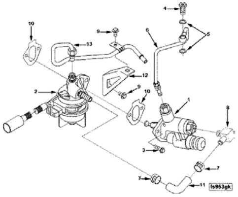
1998 12-Valve illustration. Part number 13 differs on 1994-1997 designs.
The fuel exits the lift pump through a metal tube to the fuel filter base inlet. It then is filtered and exits the outlet of the fuel filter assembly to travel to the injection pump. It is desirable to see 25psi at the fuel filter inlet. If you notice more than a 5psi drop across the filter (inlet to outlet) the filter is likely causing restriction. When testing the lift pump, should more than 4.0 inch Hg be shown on a vacuum gauge an inlet restriction exists somewhere back at the fuel tank. There are several things to watch for when servicing your fuel filter. The spin-on cartridge used in ’94 to ’96 vehicles (Fleetguard FS1253) has three o-rings that require attention when installing the filter: one on the re-usable water in fuel sensor, one that contacts the filter base and also one that fits onto the filter nipple. It’s not a bad idea to check that the filter nipple is tight in the filter base with a hex wrench.
Fuel Filter
| 1994-1996 | 1997-1998 |
| Spin-on cartridge w/removable fuel drain/WIF (water in fuel sensor). | Drop-in cartridge. Filter cartridge canister housing contains a fuel drain and WIF sensor. |
On the drop-in style cartridge used in ’97 and ’98 vehicles (Fleetguard 19598), the o-ring on the canister housing’s threaded shaft (just below the brass bushing) is sometimes omitted from a filter kit. Should that be the case it is an acceptable practice to reuse the existing o-ring.
The fuel then travels from the filter outlet to the Bosch P-7100 fuel injection pump. This concludes the delivery portion of the tour of the low-pressure fuel system. However, several other items are worth mentioning on the return circuit of the fuel system. On the backside of the injection pump near the front corner of the pump is the location of the Bosch P7100 fuel pump overflow valve. This valve opens and allows fuel return to the fuel tank at approximately 22psi. When diagnosing fuel pressure problems, one can often determine if a lift pump or overflow valve problem exists by doing the following test. Let’s assume we see a 12psi reading on our fuel pressure gauge. With the engine idling and a pressure gauge attached, slowly squeeze the rubber return line (this infamous rubber fuel return line is often problematic, but more on that subject in a minute) that runs behind the fuel filter. If the pressure gauge starts to rise, it means that the lift pump is making good pressure and that the overflow valve may be opening too soon. An overflow valve that opens at too low of a pressure will result in poor performance. Too much fuel will return to the fuel tank which robs the injection pump of fuel pressure that is necessary for proper operation. If the line pinch test makes little or no difference on the fuel pressure gauge, it would suggest that the lift pump is weak.
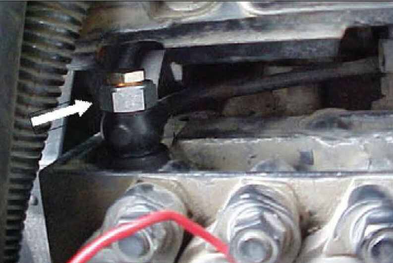
The Bosch P7100 over-flow valve.
A drain manifold is available for excess fuel not injected by the six fuel injectors. The return path is sequential at each injector and returned to the fuel filter inlet. Usually these will leak fuel noticeably if a problem occurs, allowing the owner to quickly pinpoint the leak.
Last, but not least (as evidenced by the numbers of problems that this hose has caused) is the rubber fuel return line. The illustration shows the rubber line used on a ‘98 12-valve. The ‘94-‘97 trucks use a rubber line (5/16”) that is about three times as long. The illustration is misleading. This hose is very difficult to see and access as it is tucked behind the fuel filter assembly.
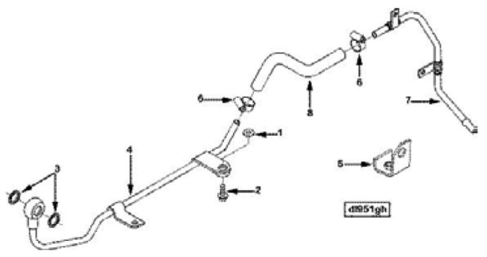
Notice the return line parts diagram: (illustration for 1998 12-valve).
Part number 8, rubber fuel return line, is about three times as long on the earlier 12 valve applications.
Also, part no. 7 is different as well.
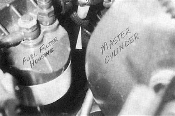
Look closely, this picture from Issue 29 attempts to show the rubber fuel return line.
Engine heat and age will cause this hose to develop cracks. It will leak air first, then fuel. Many owners report the use of a silicone grade marine fuel line as a permanent repair. I’ve had good luck as well with a Gates fuel injection hose, which seems to withstand the heat and elements far better than the factory-supplied SAE J 30R7, rubber fuel line. I find it helpful to remove the fuel filter base from the engine when changing the rubber return and/or supply lines. The lines can be gently slipped out of the brackets at the bell housing to provide better access. I also like to have a fresh razor blade handy to split the old lines where they are often stuck onto the metal fuel piping. Some fresh stainless steel clamps are smart too.
I will leave you with a list of part numbers that may help you in sourcing parts. Be advised that the part numbers may have been superseded.
Andy Redmond
Redmond Enterprises and Engine Repair
Plano, Texas
(972) 398-3934
Common part numbers:
| Part | MOPAR | Cummins | Other |
| Lift pump | 5012209AB | 3936316 | |
| Lift pump gaskets | 5014230AB | 3931059 | |
| Injection pump overflow valve | 4883838AB | 3932096 | 2417413093, now ends in 101 (Bosch) |
| Gaskets for overflow valve | 5015576AB | 3935171 ? | |
| Metal return line (over flow to rubber line) | 4746641 | 3923171 | |
| Fuel filter to injection pump (metal line) | 3936691 | ||
| Rubber elbow (fuel heater to lift pump) | 4883978AA or 4746638 | N/A | |
| Sending unit (fuel) - 1994-1997 | 04797738 or 05013467AA | N/A | |
| Sending unit (fuel) - 1998-2002 | 4897669AC | N/A | |
| Roll-over valve (fuel module) | 52127666 | N/A | |
| Roll-over valve grommet | 4002149 | N/A | |
| Pre-filter screen kit | 4762962 | 3845400S (Fleetguard) | |
| Fuel heater to heater base (upper) | 3834185S (Fleetguard) | ||
| Fuel heater element | 3907766S (Fleetguard) | ||
| Fuel heater harness | 3843722S (Fleetguard) | ||
| WIF (water in fuel sensor) 1994-1996 only. | 3831852-S (Fleetguard) |
Originally published in Turbo Diesel Register Issue 49
August/September/October 2005


