Your Dodge Ram's A/C System
Are the summer months in your truck spent with the old-school “2-60” air conditioning (two windows down at 60mph)? A properly operating HVAC system provides comfort and safety. The pages of many prior issues of the Turbo Diesel Register magazines have been devoted to the removal of the instrument panel to replace a leaky air conditioning evaporator core (‘98-‘02), leaking heater core, flimsy blend air doors (‘03-current), etc. And you'll find some of the A/C parts for the DIY-er at Geno's Garage.
Instead of covering “how to change a part,” let’s discuss the theory of the system’s operation and some real world technical tips not found in your factory service manual.
Before becoming a do-it-yourself A/C expert, recognize the reason your local shop charges so much: many expensive service tools are necessary to properly repair the A/C system. A DIY repair can end up costing substantially more than a professional repair because you can’t avoid introducing moisture into the A/C system. At a minimum, a good vacuum pump, manifold gauge set, charging stand and an accurate thermometer are necessary. Charging can be accomplished with the old standby 12-ounce cans, but a 30-pound cylinder and a charging scale are needed to prevent over- or under- charging the system. If you are concerned about complying with EPA rules (those applying to professional technicians) governing the release of refrigerant into the atmosphere, add a recovery or recovery/recycling machine to your tool kit.
Some A/C Basics
If the principles of automotive air conditioning are unfamiliar, you might wish to look at the glossary of terms below for a better understanding. Always practice safety by wearing safety glasses and protecting skin from refrigerant and refrigerant oils!
How it works: Turbo Diesels have the following components: see diagram below.
Typical A/C components - Dodge Turbo Diesels (HFC 134 A)
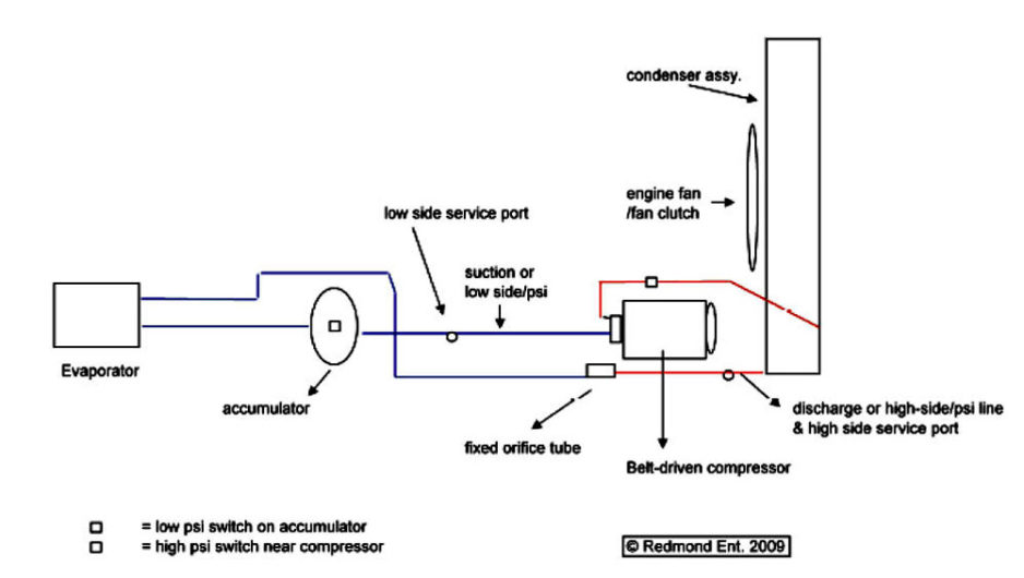
The blue lines are the suction/low side psi system operating pressures.
Principle of Operation
Although plumbing and component locations vary slightly from generation to generation among of our trucks, the concept is the same. The refrigerant pressure will be raised by the compressor and discharged as a hot, high-pressure vapor into the condenser. There it condenses and changes physical state to a high-pressure liquid. Next the high-pressure liquid is forced through either an expansion valve or a fixed orifice tube, which restricts the flow of the liquid. This reduces its pressure to approximately 30 psi. Then the liquid flows into the evaporator where the refrigerant boils to a vapor as it absorbs heat from the air blowing past the fins. The low-pressure vapor is suctioned, or drawn, from the evaporator, then through the accumulator and back to the compressor. The compressor accepts the low-pressure vapor, compresses it, then discharges the now compressed high-pressure vapor into the condenser. One cycle of the refrigeration process is now complete. The refrigerant charge level is imperative, as over or undercharging will lead to poor system performance. Pressure to temperature relations are very important, but more on this later.
Within this closed and pressurized system, calibrated amounts of the proper lubricant are added and mixed with the refrigerant. The oil’s sole purpose is to lubricate the compressor.
Important Glossary of A/C terms/components:
Compressor: A reciprocating piston or orbital scroll pump that is engine belt driven, with an electronically controlled clutch which cycles the unit on/off. Low- and high-pressure switches or sensors mounted in the refrigeration system help the control unit maintain proper system operating pressures.
Heater Core: Think miniature radiator/heat exchanger plumbed into the vehicle’s cooling system, but residing in the HVAC blower case. The hot antifreeze radiates heat, which the blower motor pushes through the ducts to warm the interior. This device uses a blower case diverter door to blend warm and cold air and/or to close the warm air compartment to improve A/C evaporator performance. If this core leaks, the sweet smell of antifreeze is often present as it soaks your carpeting, and deposits an oily film on the inside of the windshield. A clogged unit will result in poor heating performance.
Evaporator: A heat exchanger located in the vehicle cabin, in the HVAC blower case. The evaporator cools the inside of the vehicle when the blower fan pushes air across its chilled surface. (A low-pressure liquid refrigerant boils, turning to a low-pressure vapor which chills the evaporator core surfaces.) The 2003-to-present trucks utilize a thermister precisely located in the evaporator coil to prevent freeze-up, permitting more sophisticated compressor clutch cycling, which equates to better performance.
Condenser: A heat exchanging device mounted in front of the radiator that cools the hot, high-pressure vapor and “condenses” it into a high-pressure liquid refrigerant that is sent to the fixed orifice tube. Cooling is accomplished by the fan pulling ambient air through the condenser fins and also when ambient air is forced through the fins while the vehicle moves down the road.
Radiator Fan Clutch: Older Turbo Diesels utilized a belt driven cooling fan with an attached fan clutch. It becomes more or less engaged by a thermostatic valve inside, which regulates the flow of viscous fluid inside the clutch housing. The clutch should prevent the fan from spinning freely when tested by hand with the engine off. Its failure is manifested by a grease trail of the viscous clutch fluid leaking or by engine overheating on warm days. The 2003 and later trucks use an electronically controlled fan clutch, the duty cycle of which is dictated by the engine control module (ECM). Your service manual will have specifications for fan speed versus engine rpm, but a moderate to high-end ODB II scan tool is necessary to monitor this.
Expansion Device: A metering valve for liquid refrigerant. One is called an expansion valve, also known as a TXV (thermal expansion valve), which was used on the 1989-1993, First Generation trucks. The other type of expansion device is a fixed orifice tube. The purpose of both is to cause a restriction similar to a pressure regulator, turning the high-pressure liquid refrigerant from the condenser outlet into a low-pressure liquid on its way to the evaporator. The fixed orifice tube can stick open, which will flood the evaporator with a warm, high-pressure liquid, and inadequate cabin cooling will result. Should the TXV not open or the orifice tube become clogged, little or no high-pressure liquid can convert to low-pressure liquid, resulting in sub-par cooling. One test is to touch the expansion device. The evaporator side should be cool to cold; the condenser side should be hot.
Receiver Dryer: A can-like device that contains a desiccant material to remove moisture and/or contaminants from refrigerant. This part is used in systems with a thermal expansion valve. It can also store a bit of liquid refrigerant as reserve during very hot conditions/high loads. It will also be mounted so the liquid refrigerant flows through it before entering the evaporator inlet. The best practice is to replace this any time the system is opened, or during major component replacement.
Accumulator: A can-like device also containing a desiccant to remove moisture/contaminants from refrigerant, but this is used with a fixed orifice tube, not a TXV. It is mounted to receive low pressure vapors from the evaporator outlet. If any low pressure liquid escapes the vaporization process, it falls into the can to prevent liquid “slugging” which would destroy the compressor. The best practice is to replace this anytime the system is opened and/or for major component replacement.
Evacuation: “Pulling a vacuum” or emptying the system with a vacuum pump removes air and some refrigerant oil from the system, and, more importantly, will “boil” any moisture in the system. This process also provides a system leak check, and is performed just prior to recharging the system. The technician will attach the vacuum pump to the system and then open both manifold gauge valves. After ten minutes or so, the isolation valve is closed on the vacuum pump and the pump turned off. The manifold gauges should be rechecked after five to ten minutes. The same or lower vacuum reading on the low side gauge should be observed, and the high side gauge needle should be pulled down to the zero stop/pin. If not or if vacuum will not hold, a leak exists. If no leaks are noted, turn the pump on, move the isolation valve back on and continue evacuation for 10-45 minutes depending upon the size (measured in cfm) of the vacuum pump.
Charging: Process of adding refrigerant to a system. Usually the engine is off, the yellow hose from the manifold gauge set is attached to the can, charging cylinder, scale, etc. and the manifold gauges attached to the service ports. Automated recovery/recycling equipment charges the manifold gauges with refrigerant up to the service couplers. Many DIY’ers will allow some refrigerant to vent (1-2 seconds) from a slightly loose hose at the service coupler connector (which is shut off to preclude the charge from entering the system) to purge air from the manifold gauge hoses. Once the gauges are “charged,” system charging can commence. Charging can be accomplished with vapor only (can or charging cylinder stays upright); charging with liquid refrigerant (can or charging cylinder valve facing down) can cause compressor damage (liquid slugging). With the engine off, charging through both the low and high side manifolds is acceptable, but only a portion of the charge will flow into the system. Next, close the high side manifold valve to avoid compressor damage or small refrigerant can explosion, start the truck, select low fan speeds and A/C at the controls, and continue to charge vapor into the low-side port to a predetermined full charge amount.
Dye: This is fluid added to A/C system for leak detection. The dye is used in conjunction with an ultraviolet (UV) light that will expose refrigerant leaks. Some new receiver/dryers and accumulators come with a dyepack already installed.
Sealer: A sealant added to a leaking system to seal minor leaks. This usually voids the system warranty, so it should be avoided. Locate and repair the leak.
Electronic Leak Detector: This is a handheld “sniffer” that can sensitively detect refrigerant that enters its probe, alerting the user to a probable leak. There are different types for different refrigerants.
Refrigerant: These are the chemicals that change from liquid to gas and back again in various portions of a sealed A/C system with a compressor and expansion device. Two types of refrigerants are used in Turbo Diesels.
R-12/CFC -12—or chlorofluorocarbon, also known as Freon. This was used on 1989-1993 Turbo Diesels, unless they have been converted for use with R-134a (another type of refrigerant). R-12 vehicles have R-12 specific service ports so other refrigerants cannot be added. Since R-12 contains CFCs, it is banned from manufacture in the US, but significant refrigerant recycling is done at a commercial level. One must be licensed under Section 609, of the Clean Air Act (EPA) to purchase or dispense R-12.
HFC-134a – hydrofluorocarbon, an environmentally friendly replacement for R-12 used in all 1994 to present Turbo Diesels. It has a larger molecular structure, which makes it slightly less efficient than R-12. However, the EPA considers it less harmful to the environment, since they are concerned with ozone depletion. As with other refrigerants, it is illegal to vent HFC-134a.
R-12 to R-134a Conversion: Also known as “retrofit,” this conversion usually involves a kit containing adapter fittings for the low and high side service ports, O-rings, special oil, etc. Quality installers will recover the R-12/freon refrigerant, flush the system to remove the residual mineral oil, then replace all critical service O-ring seals, change the dryer, and evacuate the system. If no leaks are found, they recharge the system with the proper quantities of PAG oil and R-134a. The system’s cooling capacity is reduced about ten percent due to R-134a’s molecular structure being larger than R-12. Many of the DIY kits contain an Ester oil that is compatible with oils used in R-12 systems or with the poly-alkylene glycol (PAG) oils used with R-134a. If PAG oil is added during conversion without a thorough flushing to remove mineral oils, the two differing oils can sludge or gel, creating a mess. This would be similar to adding petroleum-based fluids to your brake master cylinder reservoir.
Venting: Opening the sealed A/C system and allowing the pressurized contents (refrigerant) to be released into the atmosphere.
Recovery: Gathering refrigerant, using purpose-built equipment, into a recovery cylinder to prevent refrigerant venting.
Recycling: Recovered refrigerant is circulated through filters to rid the refrigerant of air, oil and contaminants. This refrigerant can be used to recharge a system if the recycling machine meets SAE guidelines and has been properly maintained.
Service ports: Parts where a manifold gauge set connects to the vehicle’s A/C piping to allow the technician to charge, recover or evacuate the system. On an R-134a system, the low side service port is smaller than the high side port to prevent system contamination or incorrect manifold gauge/charging equipment connection.
Oils: A/C oil is very hydroscopic (absorbs moisture easily). Purchase a sealed container for each service, then discard the remainder in accordance with local regulations. R-134a systems in Turbo Diesels use PAG (Polyelkylene Glycol) oils. If your service manual or under-hood A/C informational label specifies ND-8, the industry correlation is “PAG 46.” Likewise if SP-20 is specified, use “PAG 100.” How much oil should I add? This is tricky; too much oil equates to poor cooling; too little, danger for compressor failure due to insufficient lubricant. Follow your service manual’s charts for each component’s oil capacity. A rule of thumb for an evacuated system that is serviced with no component change would be to re-introduce one fluid ounce of oil for losses from evacuation. If components are changed, attempt to fill each with specified amounts. For accuracy, the system should be partially disassembled and flushed with commercially available A/C solvent, fresh oil added to each component, then reassembled for evacuation, leak testing and recharging.
Seals and O-rings: The connection points of A/C plumbing are snap together, spring loc connections with O-rings on the interior flares of the piping ID to pipe OD. Usually the “green” HBNR O-rings are compatible with modern refrigerants. Use caution, and should you have to replace O-rings, be sure that they are compatible with R-134a and PAG oil.
A/C system Q & A:
Q: How does the A/C system cool the vehicle cabin?
A: The evaporator is “chilled” by the refrigerant, thereby removing heat from the air that is blown past it. As this process occurs, heat is removed from the vehicle and the cabin’s ambient temperature is cooled.
Q: Does my A/C system require annual refrigerant top-off or periodic tune up?
A: Yes and no. Annual system inspection of the air conditioner components is recommended. Coolant system inspection of the water pump, belt/hoses, fan clutch, radiator fins, condenser fins etc. should also be performed. System manufacturers specify a charging capacity, which should be followed exactly. Adding or subtracting refrigerant is not recommended, unless a leak has allowed for a low charge. Topping off is an inaccurate science usually resulting in over/undercharge, meaning an under-performing system. A chronically undercharged system will ultimately result in compressor damage due to loss of oil.
Q: If the system has been compromised (leak-down), what type of performance problems could occur?
A: If too much moisture gets into the system, the moisture can freeze in the expansion valve and stop the system from cooling. Ever ride in a vehicle and observe the A/C system “freeze-up” about 10-15 minutes after initial use? Now you know why. Also, on older R-12 systems the moisture can react with the R-12 refrigerant and form hydrochloric acid that corrodes metal parts and attacks rubber seals.
Q: How do I know when my compressor is faulty?
A: Provided the rest of the system is in specification, a compressor that won’t “pull down” low enough on the low side or build sufficient pressures on the high side would be a candidate for replacement. Often other components are working improperly, mimicking degraded compressor performance. A failed compressor will often scatter tiny pieces of foreign object debris, in which case a flush of the system is recommended.
Q: Should a faulty compressor be replaced with a new or remanufactured unit?
A: A remanufactured unit or “new unit made who knows where” may not perform satisfactorily. If you must choose a remanufactured unit, source it from your Mopar dealer. I offer new Sanden compressors and OEM quality replacement parts at substantial discounts. Most compressor warranties are non-existent without a system flush and a dryer/accumulator replacement.
Q: Can I use measurements/performance tests from residential/commercial HVAC systems to correlate to operation principals/system performance problems on my truck?
A: Yes, but due to differing refrigerant types, system capacities, etc. often many correlations are invalid. I utilize both measurements in automotive A/C system performance/diagnostic testing, but care must be taken to establish a baseline on a perfectly performing system before condemning an under performing system.
Q: What are perfect operating pressures for the low and high sides as observed by manifold gauges?
A: There are no exact answers here. Rather, there are ranges of pressures that correspond to a pressure/temperature chart.
A/C PERFORMANCE TEMPERATURE AND PRESSURE
| Ambient Air Temperature | Air Temperature at Center Panel Outlet | Compressor Inlet Pressure at Service Port (Low Side) | Compressor Discharge Pressure at Service Port (High Side) |
|---|---|---|---|
| 21° C (70° F) | 7° C (45° F) | 138 to 207 kPa (20 to 30 psi) | 1034 to 1724 kPa (150 to 250 psi) |
| 27° C (80° F) | 7° C (45° F) | 172 to 241 kPa (25 to 35 psi) | 1379 to 2068 kPa (200 to 300 psi) |
| 32° C (90° F) | 13° C (55° F) | 207 to 276 kPa (30 to 40 psi) | 1724 to 2413 kPa (250 to 350 psi) |
| 38° C (100° F) | 13° C (55° F) | 241 to 310 kPa (35 to 45 psi) | 1999 to 2689 kPa (290 to 390 psi) |
| 43° C (110° F) | 18° C (64° F) | 276 to 345 kPa (40 to 50 psi) | 2413 to 2965 kPa (350 to 430 psi) |
The inlet/outlet and center vent temperatures should only be a few degrees higher than the reading on the low side gauge face and closely correlate to the center vent temperatures. Ideally look for a temperature of 40 degrees at the center vent with the windows up, maximum fan setting, recirculation mode position setting.
Q: What are static pressures?
A: Connect the manifold gauges to the low and high service ports with the engine off. Compare gauge readings to one another and to a pressure/temperature chart for system refrigerant type. Both gauge faces should read approximate outdoor ambient temperature. If gauges differ side to side, it could indicate a low refrigerant charge. Time for a quiz (see chart below). For an R-134a system, with ambient air temperature of 90 degrees, what should the refrigerant pressure be? Did you answer 104.3 psi?
Further can you now understand why your high side gauge might read 362.7psi?
That would indicate the compressor’s hot vaporized refrigerant measures 175° on its way to the condenser.
Temperature Pressure Differential Chart
| Temperature in Fahrenheit (°F) | PSI CFC-12 | PSI R-134A |
|---|---|---|
| 50 | 46.7 | 45.4 |
| 55 | 52.1 | 51.2 |
| 60 | 57.7 | 57.4 |
| 65 | 63.8 | 64 |
| 70 | 70.2 | 71.1 |
| 75 | 77 | 78.6 |
| 80 | 84.2 | 86.7 |
| 85 | 91.8 | 95.2 |
| 90 | 99.8 | 104.3 |
| 95 | 108.2 | 113.9 |
| 100 | 117.2 | 124.1 |
| 105 | 126.5 | 134.9 |
| 110 | 136.4 | 146.4 |
| 115 | 146.8 | 158.4 |
| 120 | 157.6 | 171.1 |
| 125 | 169 | 184.5 |
| 130 | 180.9 | 198.7 |
| 135 | 192.9 | 213.5 |
| 140 | 206.5 | 229.3 |
| 145 | 219.5 | 245.6 |
| 150 | 234.5 | 263 |
| 155 | 248.6 | 281 |
| 160 | 265 | 300.2 |
| 165 | 280.2 | 319.9 |
| 170 | 298.2 | 341 |
| 175 | 319.7 | 362.7 |
| 180 | 338.7 | 385.6 |
| 185 | 358.6 | 409.7 |
Q: How do I test for leaks?
A: One method is to visually inspect the components and connections for tell-tale signs of oil accumulation, a sure sign of a larger leak (see photo). Other methods include adding a system dye (usually just an ounce or so), allowing the dye to circulate through the system components, then using a black light (UV) to inspect each component, connection, compressor shaft seal, etc. Finally, an electronic “sniffer-type” leak detector is useful for areas which are hard to see (inside blower cases to diagnose leaks in the evaporator cores): an alarm sounds from the tool if refrigerant is detected. Refrigerant tends to be heavier than air, allowing it to settle down. Operate the system for 15 minutes, then in a protected area out of the wind, turn the engine off and use the leak detector to locate any substantial leaks.
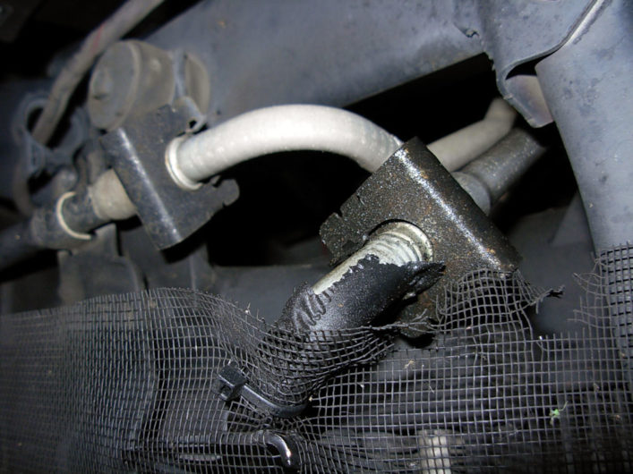
Q: My truck doesn’t overheat, but it won’t “provide any cold air.”
A: If the manifold pressures are too low on the low side and higher than expected on the high side (more than 285-300psi), I would suspect an internal system component restriction, or external component restriction, (a dirty radiator, condenser, etc.) Remember the photo at the beginning of this article? I recently diagnosed and repaired a truck that had been to two other shops. The low side pressures were low when the compressor clutch would stay engaged and the high side was 340psi, about double what it should have been. A thorough cleaning of the condenser, charge air cooler and radiator almost instantly reduced the high side pressures to 180psi. Before going down this path, some cool water spritzed on the condenser also proved my airflow theory, as the high side temps would normalize and the evaporator temps would lower. A plugged fixed orifice tube could also prevent sufficient liquid refrigerant from reaching the evaporator.
Q: Why does my truck drip water when using the A/C?
A: As the refrigerant turns into vapor in the evaporator, chilling its surface, the warm interior cabin air over the cold surface causes condensation to form. This drains into the blower case and out of the interior via the drain pipe. Many ‘94-‘02 model trucks have had wet carpet on the passenger side floorboard due to a plugged drain. An extension hose works wonders for this.
Q: Why does my truck have a buzz or rattle after the warranty repair was performed for the updated HVAC blower case actuation doors?
(Note: TSB 24-004-03 is for 2003 trucks, but HVAC blower case problems are widely experienced up through model year 2006.)
A: I recently encountered this as I corrected a sloppy warranty repair. Several things came to light. I found that the fasteners retaining the accumulator to the firewall bracket were about to fall out, which tightening helped only a little. Also, two of the nuts for the blower case-to-firewall retention studs were missing. I placed a piece of foam between the heater core inlet/outlet pipes immediately after they passed through the firewall into the engine compartment. The assistant inside the cab of the idling truck quickly roared in glee as the buzz disappeared. After looking at the parts manual, I determined that the heater core retention clamp (Mopar part #5073972AA) must have been left loose or not reinstalled.
Perhaps some of this will serve to aid you in better understanding how your A/C system operates. It should also arm you with knowledge to discern if your A/C repair facility shoots straight with their customers.
Andy Redmond
TDR Writer
This article originally appeared in Turbo Diesel Register Issue 68, May/June/July 2010.


