The Case of the $942 Fuel Filter
(or How to Change a #5 Injector)
Solving the mystery of a vehicle’s mechanical problem can require some lengthy detective work—as demonstrated in this repair that I call “The Case of the $942 Fuel Filter.” The initial complaint by the Ram Turbo Diesel’s owner provided me with scant evidence for solving the problem: “It runs good,” he said, “for a while after I change the fuel filter, but it has low power.” I doubted that the fuel filter was the culprit. But I had little to go on.
This would be a case for good ol’ Sherlock; but seeing that this is the Twenty-first Century, we will begin with some high-tech investigation. Let me walk you thru my diagnostic routine for solving this case. I opened the driver’s door and connected the computer scan tool. The following codes were retrieved:
| DTC | DESCRIPTION | COMMON TEST/REPAIRS |
| P0205 | Injector Circuit Cylinder 5 | Test wiring to injector, test injector solenoid, test ECM. |
| P2149 | Fuel Injector Group 2 supply voltage circuit/open | Test wiring to injector, valve cover gasket to ECM, ECM. |
| P0299 | Turbocharger under-boost | Inspect for air filter/inlet restriction; turbo or CAC leaks, map sensor/map sensor wiring, turbo wastegate actuator. |
| P0483 | Cooling fan rationality check | Wiring to fan clutch, fan clutch, ECM. |
Next step was to pop the hood to see what lies in the engine compartment. Not a pretty picture. When I checked fluids, I found the engine oil was black and diluted, but not overfilled. The batteries were mismatched and failed a load test. The terminals were fouled, in a mess resembling a failed high school science experiment. I cleaned the terminals and replaced the batteries.
The truck was started and allowed to idle until it came up to operating temperature. Hmm, I deduced that the engine miss was likely the cause of the low power. At normal temperature, I used the scan tool to perform an injector kill test, one cylinder at a time. Little difference was noticed on cylinders when the number 5 injector was “killed.” When other cylinders were actuated “off,” the miss became worse, an indication that those cylinders were okay. Next I performed the cylinder contribution test to check for any cylinders over/under compensating. Both tests are quite useful to learn what the engine electronics see and also to monitor the injectors’ operating parameters. Many of you are probably correlating these scan tool tests to one that many of us have used on old-school gasoline engines—pulling one spark plug wire at a time in an attempt to locate the dead cylinder. Not quite as reliable, but often used, is to measure the exhaust manifold temperatures with an infrared thermometer to locate the cooler exhaust port and thus the faulty injector. Other folks will remove the injector solenoid wires. Be cautious with this technique, the ECM’s high side injector driver has capacitors to store/raise voltage from 12 to 90-volts. The high voltage is necessary to actuate the injector when the low side driver provides a ground.
Most shadetree mechanics would install an injector at number five cylinder and most likely guess right. Elementary, you might say. But what if we replace the injector only to have the code return, or the miss remain? Still uncertain?
However, it is easy to eliminate some of the other possibilities, so they are worthy of mention. Most of the sensors on your truck are considered 5-volt sensors. The ECM transforms the 12-volt to a 5-volt reference for these sensors. Often they are a three-wire sensor: a power wire (5v), a ground wire, and a signal out wire. Very often the powers and grounds are wired as a series circuit (various sensors share each the power and ground, but not the signal). Therefore, a seemingly unrelated sensor can short and cause a problem in another circuit. We’ve all experienced Christmas tree bulb failure, causing a string of lights to go out, right?
My quick sensor check for the misfire was to independently disconnect/reconnect several sensors to which one of our DTCs might apply. These were the electronic cooling fan clutch (P0483), turbocharger wastegate solenoid and map sensor (P0299), neither of which cured the miss. (Use caution: if we didn’t have trouble codes for the items disconnected/reconnected, we likely induced some. Don’t be thrown off the path by self-induced problems.)
So now we know which of several things are not the problem, it is time to complete the logical process and make the repair. The factory service manual becomes invaluable, accessed via either the CD ROM or fee-based online literature from Chrysler TechConnect. Most serious wrench-turners know that factory manual trouble trees can be time consuming and sometimes lead to an erroneous conclusion by end of testing. They are however useful for wiring pin-outs and suggested circuit tests. Chapter Nine: Engine/Electrical Diagnosis-Diesel was consulted. The tests for both the P0205 and 2149 were followed. These were quite a laundry-list of problems that could cause these codes, including bad injector, bad wiring, bad wiring terminal pins, bad valve cover (thru cover wiring) or a bad ECM (engine control module).
If the oil is overfilled or there is fuel dilution, the engine can be briefly restarted. With the valve cover removed, one can observe any fuel leaks into the valve train. A split injector body will often “fog” fuel at the leak point. Prepare for minor engine oil spatter.
Don’t stop your testing yet. Although we have identified a component failure (bad injector solenoid coil), consider that multiple faults or a wiring problem might have caused the injector coil to fail. Notice the rearmost valve cover gasket wiring/connector. The ECM set the 2149 code when it realized something was wrong with bank 2 injectors (numbers 4-5-6). Make sure the wiring harness is serviceable from the terminals back to the ECM.
Ohm Testing Versus Voltage Drop Testing
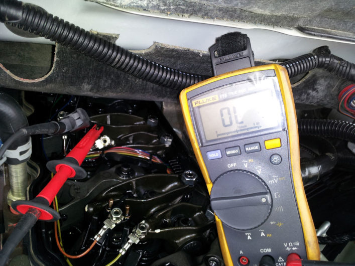
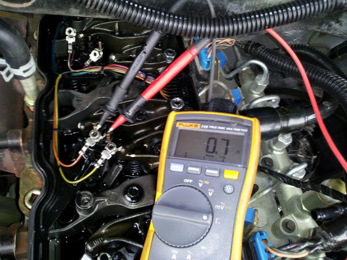
In past issues, I have preached the importance voltage drop testing. Why? Consider this: If most of the copper strands are broken in a section of wire with no apparent insulation damage, it will pass an ohm test with ease, since continuity exists. But, with broken strands the wire has little ability to carry the circuit current necessary to power the load (in our case the injector solenoid).
It is quite easy to perform a voltage drop test. Disconnect the electrical connector at the ECM and also the injector. Add a jumper wire, connecting one end of the jumper to the positive battery terminal and the other end to the disconnected injector wire. Locate the opposite end of the circuit for the same wire (ECM). Source an appropriate male terminal pin and a large automotive or headlamp bulb and wiring pigtail for your bulb. Connect the male terminal pin to one leg of the bulb holder pigtail and the other leg to ground. Is the bulb/lamp bright (circuit has little to no voltage drop)? If it does not illuminate or if it dimly glows then excessive voltage drop exists in the circuit. Still the doubting Thomas? Then use your multimeter (set to DC volts) connecting it to battery positive and negative, take a measurement (example: 12.70 volts). Next leave the black lead attached to the battery negative, moving the red lead to where your light bulb is attached. It should be within 0.5 volts of the battery voltage tested. The meter is telling you what the light bulb indicated, i.e., when it glowed dimly there was lots of voltage drop, or a bright lamp indicated little voltage drop.
In our test, the wiring tested perfectly, leading me full-circle to the only apparent problem—a failed injector solenoid causing both the P0205 and P2149.
Injector removal tips/tricks
The procedure will differ according to model year and engine (early/late 5.9 and 6.7 engines): For details consult your service manual.
TORQUE CHART
| '03-'04, 5.9L | '04.5-'07, 5.9L | 6.7L | |
| Connector tube nut | 37 ft. lbs. | 37 ft. lbs. | 37 ft. lbs. |
| Injector retention bolts - see manual procedure | 44 then 89 in. lbs. | 44 then 89 in. lbs. | 44/71 in. lbs. 44/89 in. lbs. ** |
| Injector wiring nuts | 11 in. lbs. | 11 in. lbs. | 11 in. lbs. |
| Injector line (tube nuts) | 22 ft. lbs. | 22 ft. lbs. | 22 ft. lbs. |
| Exhaust valve rocker bolt*** | 27 ft. lbs. | 27 ft. lbs. | 27 ft. lbs. |
| Intake/Exhaust valve -- pushrod adjuster locknut-- *** | 18 ft. lbs. | 18 ft. lbs. | 18 ft. lbs. |
| Rear engine lift bracket | 56 ft. lbs. | 56 ft. lbs. | 56 ft. lbs. |
*Many performance shops recommend 42 ft. lbs. to prevent connector tube torque loss.
** Some years of 6.7 show max torque of 71 in. lbs. See four step injector torqing procedure in manual.
*** Check valve lash and set to .010”—intake/0.026” exhaust
Attend to the following:
- Thoroughly clean the engine compartment to avoid contaminants from entering the open engine and/or fuel system.
- The molded wiring/valve cover gasket assembly is easily damaged, so disconnect/remove it before attempting injector removal.
- The injector solenoids are easily damaged by over-tightening the terminal nuts.
- The injector line, connector tube nut, connector tube, exhaust rocker arm and rocker arm bridge must be removed before injector hold-down bolts are removed and attempts are made to remove the injector.
- Often when the injector is lifted out of the head, fuel will leak into the cylinder. It is necessary to vacuum the fuel from the cylinder or a hydro-lock will prevent engine rotation. Joe Donnelly’s flex tubing and a piece of metal brake line tubing work well.
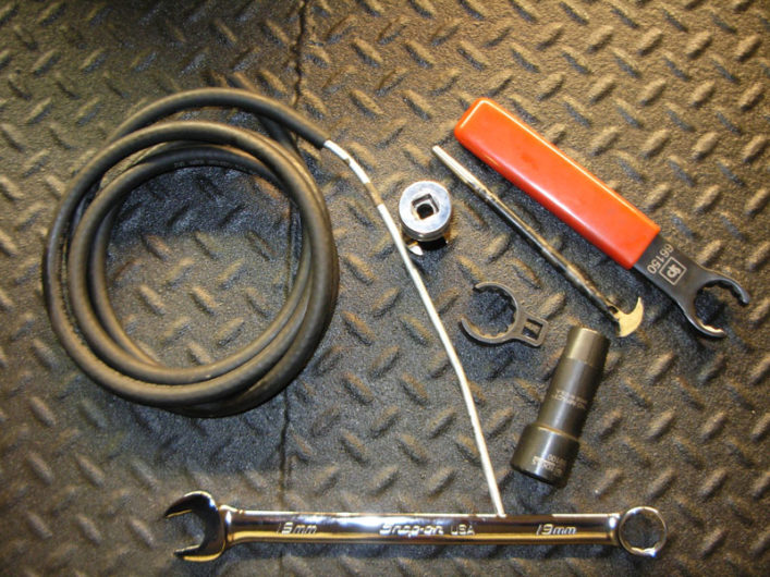
Specialty Tools:
- Schley 24mm (#66150)
- Small lady foot prybar (tool store/truck)
- Tubing/brake line “vacuum” to remove fuel
- 24mm flank drive crowsfoot
- Snap-On FRXM19 (chrome line nut socket
- Schley # 99100 (black line nut socket)
- Snap-On Box/Combo 19mm
Required tools:
- 10mm socket
- 10mm box combination wrench
- 8mm socket
- 24mm socket
- 3/8” drive torque wrench
- ¼ or 3/8 drive Inch Pound torque wrench
- 15mm socket (rear engine bracket)
- Ratchet and 3” extension
- 19mm box combination wrench.
Conclusion
In summary, this “Case of the $942 Fuel Filter” recounts the repair of this truck for engine missing and low power. Hopefully, now enlightened by my story you’ll be better prepared for any injector problems you may encounter.
Andy Redmond
TDR Writer
Article originally appeared in Turbo Diesel Register, Issue 80.


